ELECTRONICS REFERENCES IF NEEDED; WILL OPEN IN SEPARATE WINDOWS: |

See NEXT PAGE; More soldering connections >>> |
Regal Lap Steel Flamed Maple Veneer Deco Great Depression - WWII era Page 21; 12-15-10' Fine soldering componanats into circuit: |
My graphics hard drive got fixed; So here's resuming documentation of work on this Lap Steel: |
See NEXT PAGE; More soldering connections >>> |
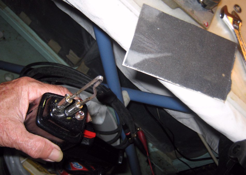
Having a clean and freshly tinned soldering iron tip is imperative for a clean soldering job; Otherwise solder will not stick to the soldering iron properly for positive control of melted solder's grip on the tip. To freshen the tip if not already freshened; First file or sand off the carbon black residue on the tip left from previous work; Leaving fresh bare metal for the solder to stick to in the next step, tinning / sizing the tip. Here is sanding the tip down to fresh metal: |
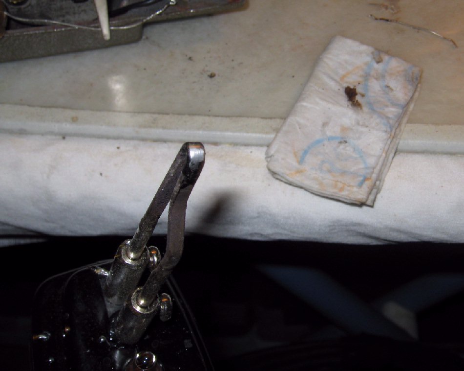
Once the tip is cleaned down to bare metal, melt a moderate drop solder onto the hot tip of the soldering iron and quickly & briskly smear the solder onto the tip in a one-direction wiping motion with a generously damp rag or paper towel. The wiping pressure & motion and steam from the rag will fine-clean the tip and force willing solder into the tip's fresh & open molecules. |
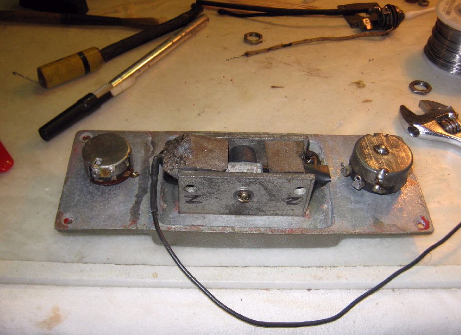
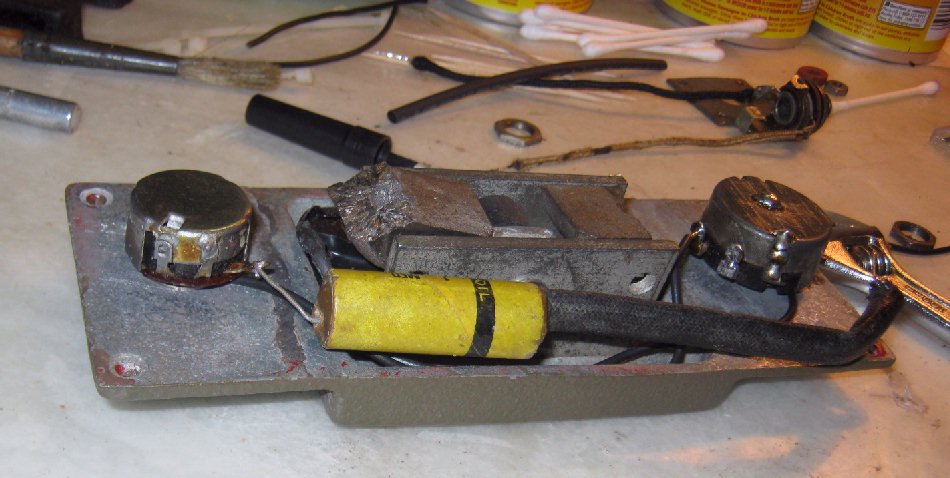
Pickup and pots ready for their wiring. |
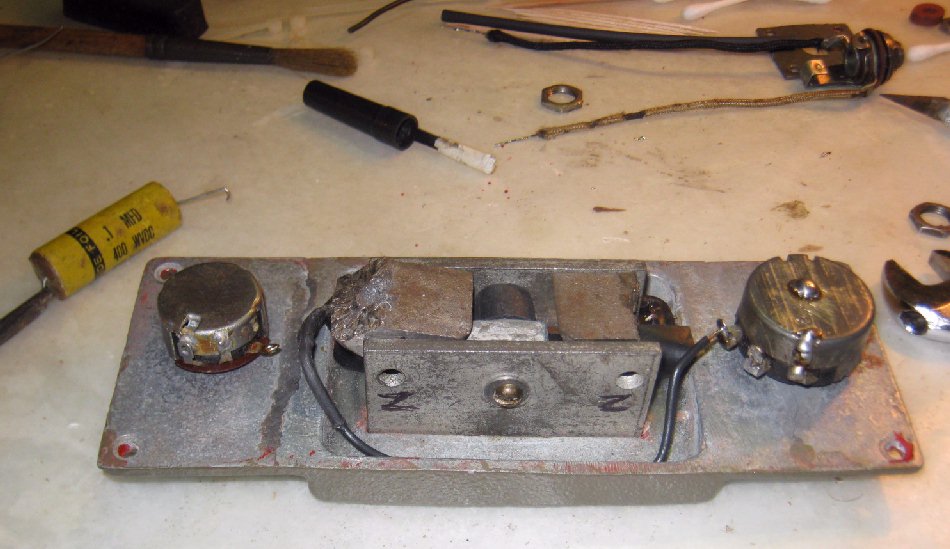
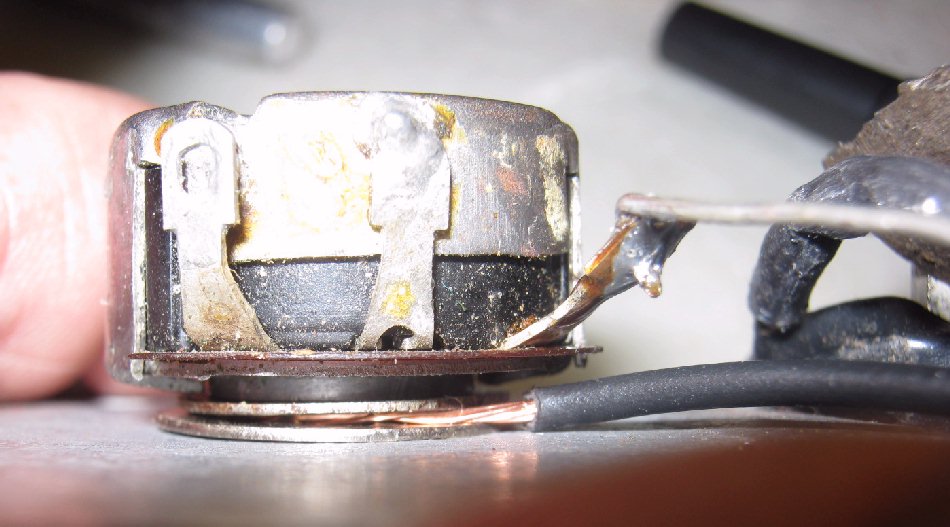
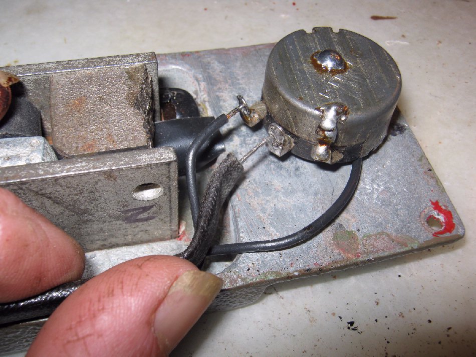
Pickup's single lead soldered to the volume pot "input". |
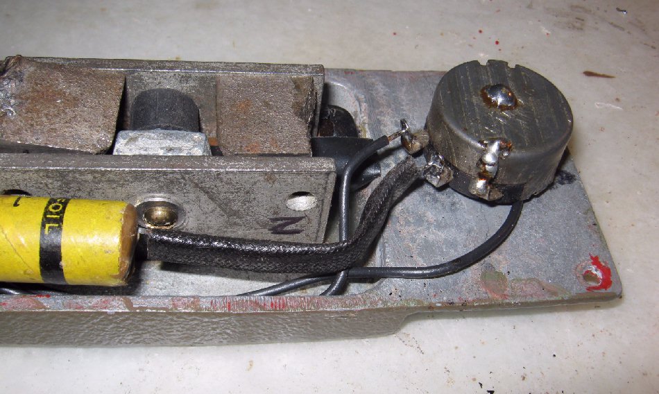
The pot metal casing acted as case ground; But since the casing was shattered and I repaired it with epoxy, and thus case ground could not be communicated through the epoxy; I ran a ground continuity wire between the 2 pots shaft mounting sleeve which now serves as case ground between the pots. |
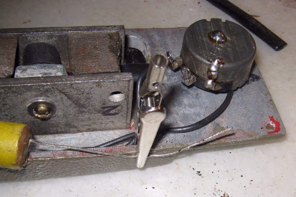
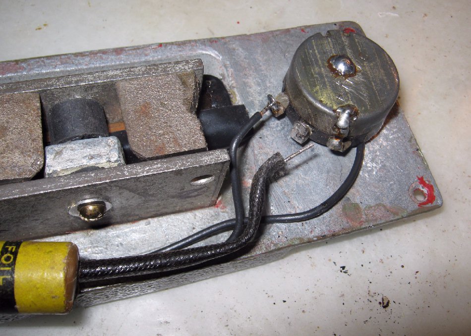
Tone pot side of the filter capacitor is soldered to the tone pot "input". The cap's other lead has a loose insulation sleeve that I bent with the end of it's lead wire to keep both together in place. Notice the case ground wire runnng between the pots. |
< |
TONE |
VOLUME |
ELECTRONICS REFERENCES IF NEEDED; WILL OPEN IN SEPARATE WINDOWS: |
Tinning the pots leads (priming the tips of the wires) requires a heat sink, ....alligator clip here, ....otherwise the wire would carry the heat into the waxed paper capacitor and most likely ruin it. |
Lugs grounded to case. |
Lug of the unused side of pot wiper, is grounded to case. |
Insulation sleeve put back on cap lead and both trimmed and bent into place for soldering onto the center lug. |
Bending a little spring pressure onto the wire in place will make the wire move right into the lug when a drop of melted solder is applied. |
Cap lead soldered into place. |