All pages of this Scorpion project Copyright 2006 WDTurner --- All rights reserved *All non-profit / non-commercial educational Mandatory Fair Use must include full credits. All use under Mandatory License must comply fully with law & rules. No other use is permitted without license or written permission. W.D. Turner is most generous to Education, small business and start-up enterpirse purposes. |

NEXT PAGE: Electronics Repair |
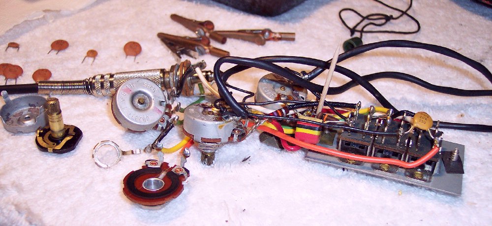
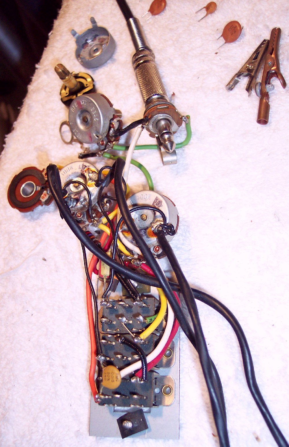
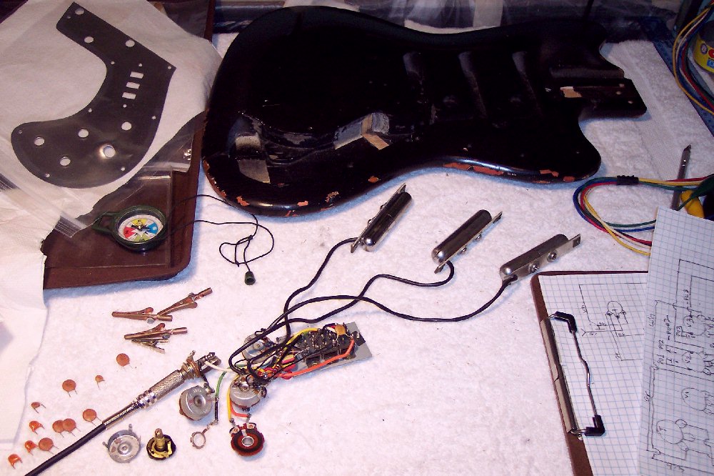
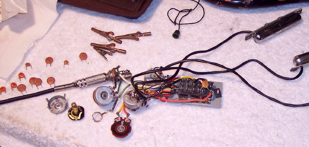
1968 Danelectro, Dane series, D3N12 Scorpion Electronics Assembly, Analysis, Troubleshooting and Work. Views of electronics harness, problems, schematic, and signal path & switching logic. Very high resolution pictures available on request |
1968 Danelectro, Dane series, D3N12 Scorpion Electronics Assembly, Analysis, Troubleshooting and Work. Views of electronics harness, problems, schematic, and signal path & switching logic. Very high resolution pictures available on request |
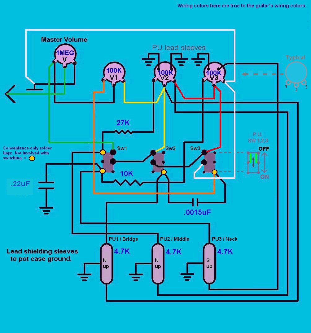
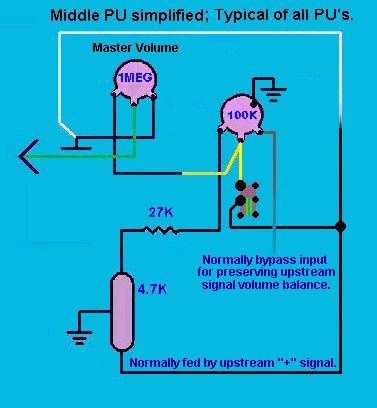
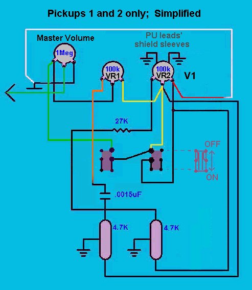
Signal Path, Switching and Bypass Logic. Schematic simplified; The convenience-only solder points on switches are removed and those wires drawn direct here; ie. only the functioning switch connections are shown here. |
PLEASE NOTE: These webpages are under construction and their meanings incongruent until finished. |
NEXT PAGE: Electronics Repair |
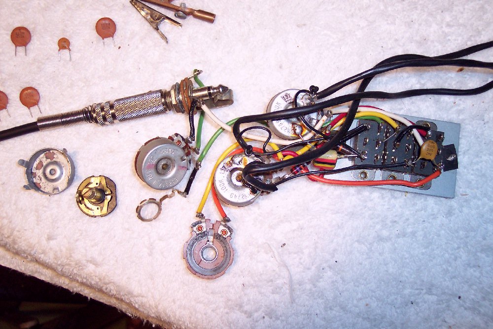
100K volume pot #1 found to have a crack in internal phoenolic plate; Opened up for inspection and shown above. This is in addition to 1Meg pot repair. 100K pot will be replaced when that point of reassembly becomes critical if a correct race cannot be found to repair this original pot. |
Repairable crack in phoenolic plate; Running from about 8: o'clock position to 1:30 position above. Unrepairable carbon pile resistor / race is also damaged from the crack's stress on the race. |
^ |
Pots are CTS; The broken one made the first week in 1967, the closest date found for the Scorpion's manufacture some time thereafter. Code: HM2749 100K 137 6701 |
Toothpick is standing-off wires for full camera view of componanats in other pics here. |
Calling all vintage CTS pot Angels. Check your bins; 1964 to 1st week of 1967 ! |
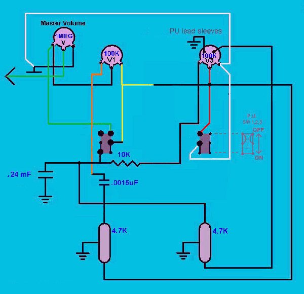
Schematic. (Scroll down for signal path, switching & bypass logic. |
Pot casing |
Wiper |
Center tap race |
Carbon pile resistor / race |
^ |
For anyone as perplexed as I was; This is a 1960's polystyrene capacitor, consumer grade color code system = .22uF, 20% tolerance and 250 Volts. Red = 2 Red = 2 Yellow = x5(^+10)pF = x6(^-10)uF. Black = 20% Red = 250V |

Pickups 2 and 3; simplified. |
Pickups 1 and 2; simplified. |
.22uF |
.22uF |
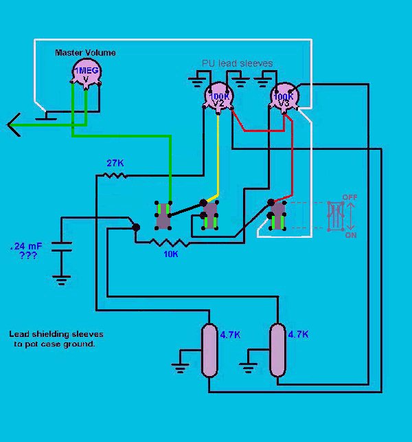
Taking pickup combos out of the picture for a clearer view: Schematic wire colors here are true to the guitar's wiring colors. Notice that turning OFF any pickup's swith does NOT simply lift continuity for that pickup; What it does is provide a single path that (1) short it's pickup's ground-side lead to it's hot-side circuit, ...and (2) provide a bypass path for the upstream signal to bypass the switch's pot / pickup and send the signal to the downstream signal path. Conversely, switching a pickup ON lifts the switch path that (1) shorts the pickup to itself and (2) bypasses upstream signal to downstream signal path. |
Pickups 1 and 3; simplified. |
Pickup 1 OFF / It's circuits invisible. |
Pickup 2 OFF / It's circuits Invisible. |
Pickup 3 OFF / It's circuits invisible. |
Bridge |
Middle |
Neck |
The neck pickup's (PU3) signal is filtered by the .22 uF capacitor, leaving pickup 3 with bass frequencies / tones. The middle pickup is not filtered and provides full frequencies with the mid-range overtones common to middle pickups. The neck pickup is filtered by the .0015 uF cap to pass-on high frequency tones. There is full frequency bleed-over carried along the signal path through the 100K pots' nominal resistance. ( I THINK that the wiring scheme of the capacitors, resistors and the pickup coils act like passive inductive crossovers similar to L-pads ...but I haven't had time yet to fully test that suspicion). ~~~ Each pickup's circuit gangs to the other pickups in series. ~~~ The neck pickup's reverse magnet serves as a humbucking pickup-half when it is ganged to Pickup 2 and/or Pickup 1. ~~~ When PU 1 and 2 are on as in the schematic above (and similar to all Pickups' switching and circuits), PU 2's hot-side circuit is routed to PU 1's ground-side circuit, while PU 2's ground-side circuit is switch-routed by SW3-OFF to the white wire on V3's lug 3 which is the route to the guitar's ground-side sleeve at the guitar's cord jack. Were PU 3 also switched on, it's switch would lift PU 2's ground-side route to V3 lug 3 and thus PU 2's ground-side circuit would then be fed by PU 3's hot-side circuit coming out of V3 lug 2 to join the tail of 3 pickups in series, with PU 3 providing the ground where it's ground-side lead connects to the casing of V3. ~~~ Each volume control has 2 internal circuits whose "inputs" are at lug 1 and 3 and "output" is at lug 2; The resistance in one side increasing with the turn of the knob while the other side conversely & proportionally decreases in resistance ...and vice versa. Turning any Pickup volume knob down acts like it's pickup's normal volume control in the volume channel (lug 1 "input"), but the other channel (lug 2 "input") serves as a converse volume / balance control for upstream signal coming to it, which turns the volume up for the upstream signal it's recieving while upstream signal through it's pickup volume is being turned down, ...which results in no loss of upstream signal volume because the volume of lug 1 circuit is combined with the converse volume of lug 3 on their common output on lug 2. If this bypass / balance function didn't exist then any volume control would act like a master volume for the pickups circuits ganged in series. ~~~ After much consternation studying what I thought was a circuit malfunction that I couldn't find in the "tone pot" circuit, ...I finally realized that the 1 Meg pot is not a tone control at all but is a Master Volume. Tone is achieved by using the 3 pickups' volume controls like a 3 band EQ! As any pickup's volume is changed, only the volume of it's circuit (and thus it's tone contributon) is changed, ...while the volumes and tones of the other pickups's circuits remain stable / unchanged. The guitar's electronics parts will serve to rewire the circuits to conventional switching and tone filtering, BUT I would personally much prefer to keep the circuit as is, play it for awhile and learn what Nate's idea was by controlling total tone via this 3-band EQ + Master Volume type circuit idea. The options of voicings with this guitar's circuits is exceptionally well suited for 12 string guitar. |
NOTICE: This circuit is still under study and the info below subject to changes discovered: |
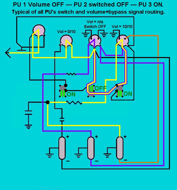
Pickups in series' upstream ground source. If PU 3 were switched off the switch would route ground source in series to the next downstream pickup that was switched on. Typical of any pickup's switch. Signal path of PU 3 with it's switch ON and volume 10/10. Bypasses PU2 circuit via Sw-2OFF rerouting. Bypassed at PU1's V1 volume set to 0 thus V1's balance-bypass is conversely at 10. PU 2 switch OFF grounds it's 2 PU leads to each other killing the PU, AND; Provides a bypass signal path for upstream signal (PU 3 circuit) to get to downstream signal path (PU1's V1 bypass side). If PU1 volume were at, say, 7, ...then PU1 would get full signal from Sw2 bypass to PU1's ground-side lead in series, send it to the PU1 volume side of the pot set to 7, while a bypass V1 volume of 3 would come from the same Sw2 bypass, equaling a V1 output of (PU 1 + 3 = vol 7) + (PU3 bypass vol 3) = PU1 vol 3 + PU3 at it's full V3 setting. PU 1's volume being down to 0 makes the other side of Pot 1 have a volume of 10 at the pot's "output" center lug, providing signal bypass balance to go to the Master Volume. If PU 1's volume were at, say, 6, ...then the bypass side of the pot would be at volume 4 and the two would equal 10 at the center lug "output" of the pot going to the Master Volume. The volume level going into either side of V1 (and any other PU's pot) is controlled by the upstream PU's volume settings. |
ON |
OFF |
Schematic colors here are illustrative and not true to guitar wiring colors: |
V1 |
V2 |
V3 |
Master Volume = 10/10 |
Sw1 |
Sw2 |
Sw3 |
Vol = 0 |
Vol = 10 |
OFF Short PU & bypass it. ------------------ ON Lift short. Lift bypass. |
Material here is Copyrighted *ALL RIGHTS RESERVED |
All pages of this Scorpion project Copyright 2006 WDTurner --- All rights reserved *All non-profit / non-commercial educational Mandatory Fair Use must include full credits. All use under Mandatory License must comply fully with law & rules. No other use is permitted without license or written permission. W.D. Turner is most generous to Education, small business and start-up enterpirse purposes. |
Output Jack |
Output Jack |