NOTICE: The wiring of this Steel was found to be incorrect, ....some previous owner's experiment or mistake. So SOME of the WIRING information on this page is incorrect, ....requiring the Steel to be re-disassembled and rewired correctly. See the CORRECT wiring schematics provided below or on a separate Correct Wiring page. I am leaving the incorrect scematic posted for reference to a previous owner's incorrect wiring in the pictures, which can reconcile pics of the wiring in the pickup-lead work being done on this page. |

More looks at the Electronics and Pickup Repair >>> |
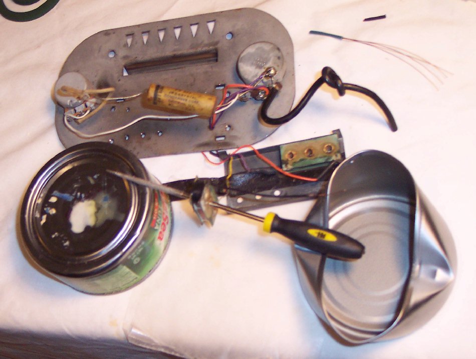
1953 Valco El Grande Steel Guitar Customer's Work Progress Reports ~ Page 6; Electronics Refurbishing ~ |
More looks at the Electronics and Pickup Repair >>> |
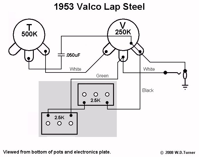
Here's a technical schematic of the WRONG way this Valco was incorrectly wired; Not discovered until later. |
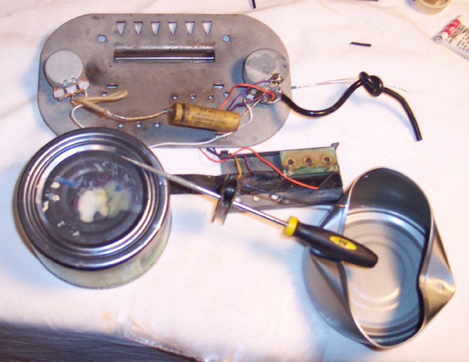
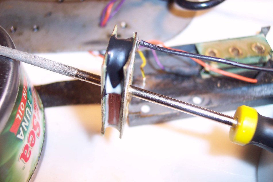
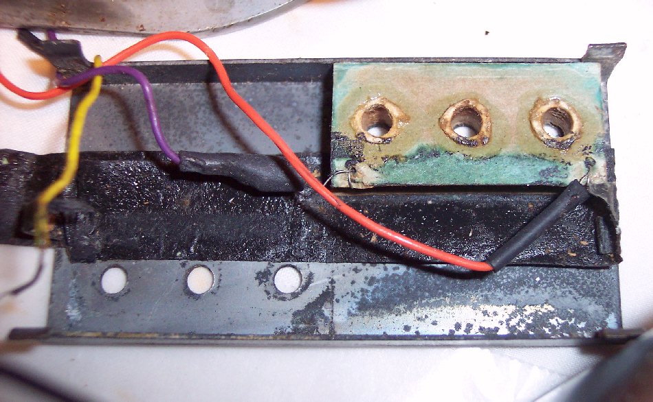
A pickup lead wire had a bad contact upon one of the two coil's end-wires. The following pictures are after the reattachment of a new lead wire to that coil. The coil is hanging from a diamond file ran through one of the coil's holes. When the pickup is assembled, those holes surround the strings sensitivity screws that thread into the electronics baseplate which is magnetized when the magnets are in place. That coil is hanging on the file for the drying of white carpenters glue used to seal and stabalize the coil's old / aging paper bobbin, and to reseal my retaping of the coil where the end wires exist the coil. ------- These photos also provide some details of the Steel's electronics. Additional details text will be provided as time & work priorities allow. |
Shown below is the pickup casing with one coil in place. The position / orientation of the coil being worked on here relative to the other coil, ....is rotated 180 degrees from each other, flipped upside down from each other, and their start / stop coil-end wires (pickup leads) are wired into the cirucuit opposite each other. The coils are wired in parallel into the circuit. NOTE: Although it can't be seen in the picture below that is missing the coil being worked on; It is worthy of note and interest to say: The relative orientation of the coils does NOT put the coils output out of phase with each other, as it appears to when first analyzing these pickups; but should put them IN phase in a humbucking orientation. One coil being upside down and rotated 180 degrees from each other has the same effect upon the pickups magnetic field as magnets being opposite polarity for each coil in more common humbucking pickups; But voila, we get humbucking here once each coil's leads is reversed to put signal back in phase with the other coil. There might be other design engineering reasons for this orientation, such as tone nuances in the polarity orientation of start / stop end wires and coil winding dirctions, especially in humbucking pickups. However, it was common but mistaken thinking even among guitar technicians until relatively recently, ...for them to think that a pair of humbucking coils had to be reverse wound from each other ......although that is not true, when all that is required of the coils is that they be wired into the circuit opposite of each other to put opposite magnetic pole polarities back in phase with each other. The reverse wound coil idea and mistaken thinking probably originated by the old original designers' knowledge of tone nuances in winding the coils opoposite (start / stop wire-end polarity) in humbucking arrangements. The in / out of phase wiring polarities of the leads into the circuit for humbucking is a no-brainer ......only the coil winding direction reasons have been mistaken by many. Or even for single coil pickups the winding direction for some particular guitars, and wiring polarity of start / stop leads, subtly effects the tone character of the pickup, ....although such coil polarity tone nuances are spokem much more of, by knowledgeable technicians, relative to humbucking pickups. |
NOTICE: The wiring of this Steel was found to be incorrect, ....some previous owner's experiment or mistake. So SOME of the WIRING information on this page is incorrect, ....requiring the Steel to be re-disassembled and rewired correctly. See the CORRECT wiring schematics provided below or on a separate Correct Wiring page. I am leaving the incorrect scematic posted for reference to a previous owner's incorrect wiring in the pictures, which can reconcile pics of the wiring in the pickup-lead work being done on this page. |
Incorrect wiring that existed on this 1953 Valco El Grande lap Steel. The pickup coils were wired in parallel rather than the factory series wiring. |
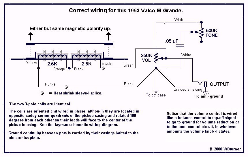
Here is a CORRECT technical schematic of the way I REWIRED this Valco. |
Here is a CORRECT wiring diagram / aka layman schematic of the way I REWIRED it. |
ELECTRONICS WORK: |
below. |
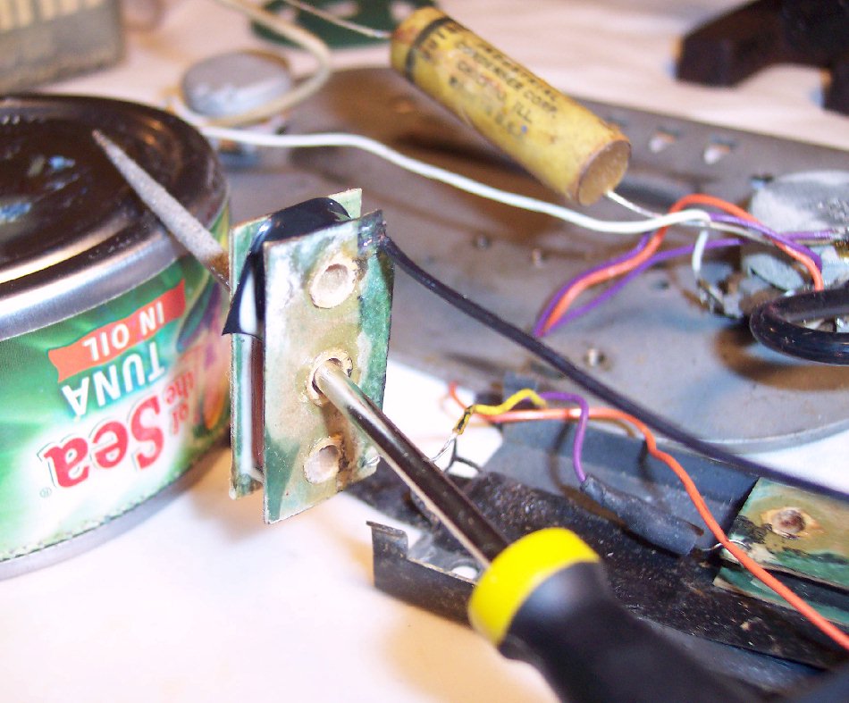
NOTICE: The WRONG color coding of the coil leads were left as they were due to the delicateness of the coils solder points and their leads. The color codes are surely not factory original, and even the leads soldered to each pickups solder points is probably not factory correct either but likely replaced incorrectly over this steel's life. |
Yellow |
Orange |
Purple |
Orange |
Yellow |
Purple |
Black |
V |
V |
V |
V |
>> = Heat-shrink splices. |
>> |
>> |